One of the strengths of cTMS is its ability to generate new types of TMS pulses. This additional flexibility requires that the traditional TMS nomenclature be augmented to be able to describe these new pulses. While cTMS offers new flexibility, it is not infinite flexibility, so a good understanding of the strengths and weaknesses will help you to take me most advantage of the device. This page will describe the typical parameters that describe the pulse and which ones are controllable and which ones are dependant on the first ones.
cTMS devices have been described in the scientific literature for several years. The design is based on the novel work by Dr. Angel Peterchev at Duke University (the first work was done while at Columbia University). Much of the nomenclature is introduced in his work and several relevant references are given at the bottom of this page.
Before describing cTMS, a quick review of traditional TMS is a good place to start. Generally, TMS comes in two varieties: monophonic and bi-phasic (and some hybrid models that combine the two). Both types of TMS start with a capacitor (and charging circuitry to charge the capacitor) and a switch (to switch the capacitor connection from the charger to the coil to discharge the capacitor into the coil). In monophasic TMS, the capacitor sends is energy into the coil. Once discharged, the current in the coil is at its maximum. The laws of electromagnetism dictate that the rate of change of the coil current will generate the magnetic field. The return path for all that energy in the coil is fed through a diode and resistor, so some returns to the capacitor and the rest is dissipated through the resistor as heat. The pulse shape is fixed, and is a function of the capacitor, coil inductance and the resistor used to dissipate the energy. The advantages are a simple system with relatively few components and from a neurophysiological standpoint, a clean pulse in that there is a single rise and decay in the electric field produced by the pulse. The disadvantage is one of efficiency. It takes a long time (in TMS terms) to recharge the capacitor from the discharged state for a new pulse. For this reason, monophonic pulses are not suitable for most rTMS applications.
Biphasic TMS is a product of the desire to perform repetitive TMS. Instead of dumping the energy to the resistor, a more complex switch circuit recycles most of the energy in the coil back into the original capacitor. This occurs in a much shorter time than discharging through the resistor, and the capacitor needs a lot less new energy to fully recharge for the next pulse since it recycled a lot of the previous pulse. This allows for very rapid and sustained trains of pulses. The drawback is that the resulting waveform is not as straightforward as monophasic pulses.
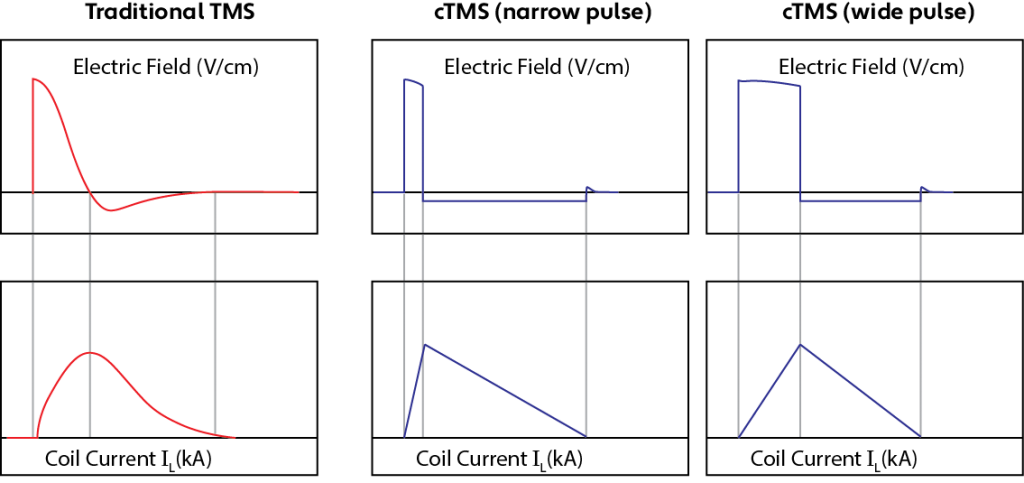
cTMS overcomes these challenges by using a completely different approach. Our cTMS uses 2 capacitors and a sophisticated switching system to juggle the energy between the two capacitors (which is a lot faster than dumping energy through a resistor). In cTMS, we define two voltages, one for each capacitor and switch from one to the other (and back again) as need be with one capacitor handling the +ve phase and the other the -ve phase. This gives us a distinct new capability. While cTMS must obey the same laws of electromagnetism as traditional cTMS, we can be more creative in how we do this. For example, we can set the voltage to whatever we wish for either capacitor and define
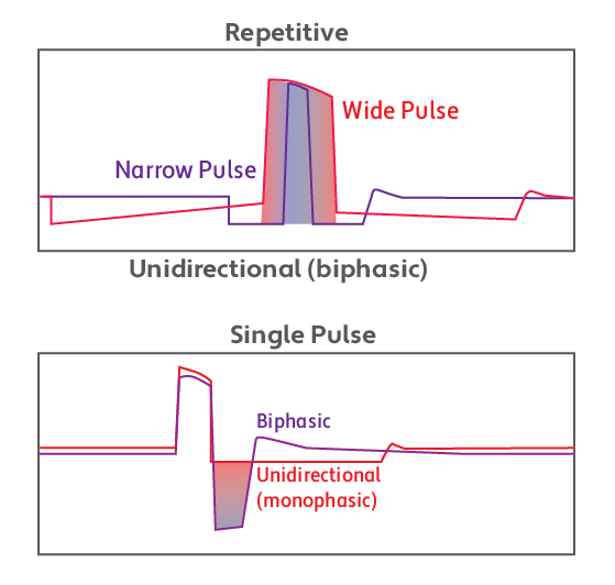 how long we connect that capacitor to the coil to control the width of a portion of the pulse. For example, by setting a low -ve voltage in one capacitor, a high +ve voltage in the other and going from one to the other and back again, we can generate a unidirectional (think monophasic) pulse.
cTMS introduces a new parameter called an M-ratio. This is a directionality control and describes the relative amplitudes of each phase of the pulse. It is the the ratio of the electric field amplitude of the -ve phase divided by the electric field amplitude of the +ve phase.
A balanced pulse is a pulse where the end voltages of the capacitors are at or slightly below the original voltages. Balanced pulses are desirable for repetitive cTMS as the time required to discharge a capacitor (that may have received a lot of residual energy) is long compared to the typical gap between pulses. This constraint can often be circumvented using a bit of creativity in defining pulses. For example, a bi-phasic pulse with an M-ration close to 1 is generally easier to balance. In cTMS, you can make the -ve phase at the start and end be shallow and long (rather than essentially equal to the +ve phase), so while it is technically a bi-phasic pulse, the effective electric field (from the neuron’s perspective) will feel very monophasic.
Selected publications featuring cTMS
Brain Stimul. 2016 Jan-Feb;9(1):39-47. doi: 10.1016/j.brs.2015.08.013. Epub 2015 Sep 1.
Enhancement of Neuromodulation with Novel Pulse Shapes Generated by Controllable Pulse Parameter Transcranial Magnetic Stimulation.
Goetz SM1, Luber B2, Lisanby SH2, Murphy DL1, Kozyrkov IC1, Grill WM3, Peterchev AV4.
Clin Neurophysiol, 127(1), 675-83 (2015)
Effect of coil orientation on strength-duration time constant and I-wave activation with controllable pulse parameter transcranial magnetic stimulation.
D’Ostilio K, Goetz SM, Hannah R, Ciocca M, Chieffo R, Chen JC, Peterchev AV, Rothwell JC
Clin Neurophysiol. 2016 Jan;127(1):675-83. doi: 10.1016/j.clinph.2015.05.017. Epub 2015 May 30.
Effect of coil orientation on strength-duration time constant and I-wave activation with controllable pulse parameter transcranial magnetic stimulation.
D’Ostilio K1, Goetz SM2, Hannah R3, Ciocca M4, Chieffo R5, Chen JC6, Peterchev AV7, Rothwell JC3.
J Neural Eng. 2014 Oct;11(5):056023. doi: 10.1088/1741-2560/11/5/056023. Epub 2014 Sep 22.
Controllable pulse parameter transcranial magnetic stimulator with enhanced circuit topology and pulse shaping.
Peterchev AV1, DʼOstilio K, Rothwell JC, Murphy DL.
Clin Neurophysiol. 2013 Jul;124(7):1364-72. doi: 10.1016/j.clinph.2013.01.011. Epub 2013 Feb 20.
Pulse width dependence of motor threshold and input-output curve characterized with controllable pulse parameter transcranial magnetic stimulation.
Peterchev AV1, Goetz SM, Westin GG, Luber B, Lisanby SH.
J Neural Eng. 2011 Jun;8(3):036016. doi: 10.1088/1741-2560/8/3/036016. Epub 2011 May 4.
Repetitive transcranial magnetic stimulator with controllable pulse parameters.
Peterchev AV1, Murphy DL, Lisanby SH.
Conf Proc IEEE Eng Med Biol Soc. 2010;2010:2922-6. doi: 10.1109/IEMBS.2010.5626287.
Repetitive transcranial magnetic stimulator with controllable pulse parameters (cTMS).
Peterchev AV1, Murphy DL, Lisanby SH.
IEEE Trans Biomed Eng. 2008 Jan;55(1):257-66. doi: 10.1109/TBME.2007.900540.
A transcranial magnetic stimulator inducing near-rectangular pulses with controllable pulse width (cTMS).
Peterchev AV1, Jalinous R, Lisanby SH.
JOURNAL OF NEURAL ENGINEERING, 11 (5), doi:10.1088/1741-2560/11/5/056023
Controllable pulse parameter transcranial magnetic stimulator with enhanced circuit topology and pulse shaping.
Peterchev, A.V., D’Ostilio, K., Rothwell, J.C., Murphy, D.L. (2014).
Abstracts in conferences:
Hannah R, D’Ostilio K, Goetz S, Ciocca M, Chieffo R, Chen J-CA, Peterchev AV, Rothwell JC (2015)
Effects of transcranial magnetic stimulation coil orientation and pulse width on short-latency afferent inhibition.
Brain Stim 8, 379-380
Hannah R, Ciocca M, Sommer M, Hammond P, Rothwell J (2014)
Continuous theta burst stimulation with monophasic pulses: effect of current direction.
Clin Neurophysiol 125, S1–S339
Sommer M, Ciocca M, Hannah R, Hammond P, Neef N, Paulus W, Rothwell JC (2014)
Intermittent theta burst stimulation inhibits human motor cortex when applied with mostly monophasic (anterior-posterior) pulses.
Clin Neurophysiol 125, S1–S339